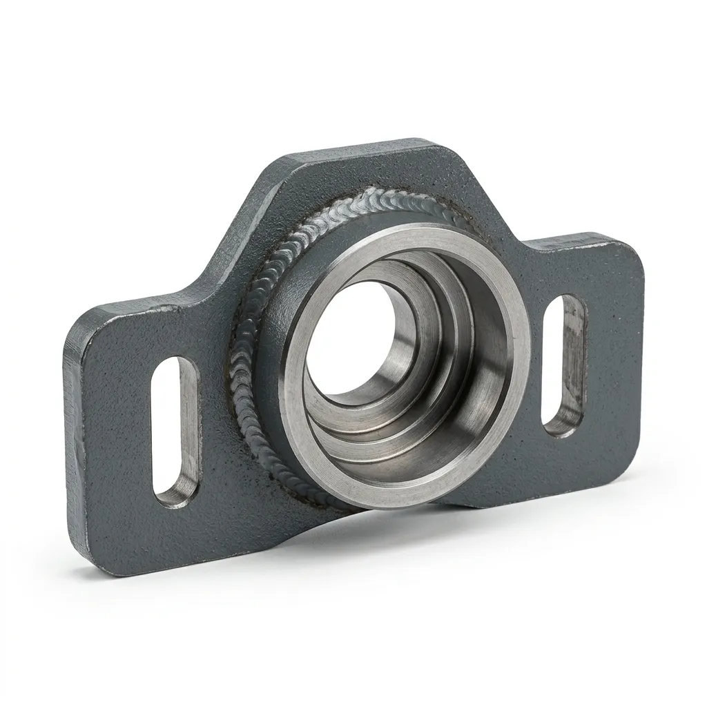
Front Bearing Housing Welding

The Front Bearing Housing Welding supports the rotor shaft in 4.0 m rotary tiller headers, using Q235B steel with H7 bore (±0.021 mm) and 0.05 mm seal-face flatness. Advantages include superior bore stability against creep, enhanced fatigue life via full-penetration welding and stress-settling, excellent corrosion resistance (≥500 h salt-spray), direct-fit compatibility, and reliable performance under heavy vibration and soil abrasion.
Product Specifications
Front Bearing Housing Welding · EVER-POWER Header Precision Division
| Parameter | Specification | Remarks |
|---|---|---|
| Product Name | Front Bearing Housing Welding | Rotor shaft front bearing support |
| Application Platform | 4.0 m Rotary Tiller / Rotavator Header Frame | Front-end bearing location zone |
| Primary Material | Q235B Cold-Rolled Structural Steel | GB/T 700 certified; yield ≥ 235 MPa |
| Housing Shell Thickness | 8 mm (standard) / 10 mm (heavy-duty option) | Heavy-duty for stony / high-vibration terrain |
| Welding Standard | GB/T 12467 / AWS D1.1 CO₂ MIG | Full-penetration at boss-to-shell joints |
| Bearing Bore Tolerance | H7 (+0.021 / 0 mm on Ø62 nominal bore) | CNC finish-bored post-assembly; CMM verified |
| Seal Register Flatness | ≤ 0.05 mm (sealing face) | 100% CMM before release |
| Overall Dimensions | Approx. 180 × 150 × 120 mm | Standard 4.0 m variant |
| Net Weight | ≈ 3.8 kg (standard) / ≈ 4.9 kg (heavy-duty) | Excl. bearing, seal and fasteners |
| Surface Treatment | Sa 2.5 Shot-Blast + Epoxy Primer + Powder Coat | Salt-spray ≥ 500 h (ISO 9227) |
| Mounting Interface | 4× M12 Grade 10.9 + 2× Ø16 locating pins | ISO-pitch header frame pattern |
| Standard Bearing Type | 6212 / 6214 Deep-Groove Ball Bearing (housed) | H7 bore; confirm bearing type at order |
| Standard Colour | Agricultural Red (RAL 3020) / Custom RAL | OEM colour matching from 10 pcs |
| MOQ / Lead Time | 1 piece / 8–16 days ex-works | OEM packing and labelling available |
Why the Front Bearing Housing Is the Drivetrain's Critical Link
On any rotary tiller header, the tilling rotor spins at operational speed because a series of bearing housings hold the rotor shaft in its designed geometric position while absorbing the loads generated by blade-to-soil impacts at every revolution. The Front Bearing Housing Welding occupies the most mechanically demanding position in this chain — it receives the front rotor shaft's bearing, which simultaneously carries the radial reaction forces from tilling-blade soil resistance, the axial forces from lateral soil flow, and the bending moment from the cantilevered mass of the rotor assembly forward of the bearing centreline. At 540 RPM PTO input in heavy clay soil, the combined peak radial load at this bearing can exceed 8 kN, applied continuously across a field day that in peak spring season routinely extends to 14 hours. The housing's job is to transfer all of this load cleanly into the header frame without allowing the bore to oval, without permitting the seal faces to lose their geometric relationship with the rotating shaft, and without cracking at the weld toes from the continuous high-cycle fatigue loading. When any one of these three functions fails, the cascade of damage that follows — outer-race creep, oil seal leakage, shaft misalignment — costs far more to rectify than the price of the housing itself.
The welded construction of this header component exists because it allows targeted material placement across the housing's geometry in a way that a uniform-wall casting cannot. The bearing boss section uses 8 mm plate to handle the high local stresses at the bore root radius. Flange sections where the loading is predominantly compressive from bolt preload use lighter 6 mm material. This zoning keeps the housing's total mass lower than an equivalent cast design at the same structural reserve — a practical advantage when front-end header weight affects three-point hitch loading on sloping paddy fields. Full-penetration welds at every boss-to-shell structural joint, combined with a purpose-built welding fixture that holds nominal geometry through the full weld sequence, prevent the distortion that would shift the bore axis after machining and compromise the interference fit that keeps the bearing outer race stationary in service.
EVER-POWER fabricates this rotary tiller part within a dedicated precision cell that sequences laser-cutting, fixture-controlled welding, a mandatory post-weld cooling period, CNC bore machining, and CMM audit in a single traceable production flow — the only sequence that produces the H7 bore tolerance and 0.05 mm seal-face flatness whose nominal values appear on the drawing but whose actual achievement requires every one of these steps to be performed in the correct order without shortcuts.
Engineering Choices That Prevent Premature Failures
The performance gap between a correctly-specified bearing housing and a catalogue-grade alternative only becomes visible after the first 200–400 hours — by which time the cost of the resulting bearing seizure, seal failure, or shaft misalignment far exceeds the original price difference. Every design decision listed below addresses a specific failure mechanism found in EVER-POWER's field returns analysis.
Post-Assembly H7 Bore Machining
The bearing bore is CNC finish-bored only after all welding is complete and the assembly has cooled for a minimum of 6 hours. Machining before welding allows the subsequent heat cycle to shift bore centres by 0.3–1.0 mm. EVER-POWER's sequence holds Ø62 bores within H7 (+0.021/0 mm) on 100% of units, with CMM verification of bore diameter and cylindricity before any unit proceeds to the coating stage. This is the single most consequential step in the entire process — and the one most commonly skipped under cost pressure.
0.05 mm Seal Register Flatness
The seal plate register face is machined to ≤ 0.05 mm flatness — ten times tighter than the general housing face tolerance. This specification exists because any deviation above 0.05 mm produces an uneven seating load on the radial lip seal, creating a gap through which soil dust enters the bearing cavity. In coastal paddy regions where fine alluvial silt is suspended throughout the working soil layer, uncontrolled seal flatness translates directly to bearing contamination and early failure.
Targeted Wall Thickness Zoning
The bearing boss uses 8 mm plate where high local stresses occur at the bore root radius. Mounting flanges use 6 mm plate where bolt preload compression, not bending, is the primary load. This deliberate zoning minimises housing mass without compromising structural reserve where it matters — a measurable advantage for header designs where front-end mass affects tractor stability on terraced hillside paddy fields in Vietnam, the Philippines, and southern China.
Precision Welding Fixture with Datum Mandrel
All sub-components are loaded into a purpose-built steel fixture that enforces nominal geometry to ±0.4 mm. Critically, the bearing boss is aligned coaxially with a precision mandrel before the first tack weld is placed — ensuring the bore axis enters the correct relationship with the mounting flanges before any welding heat is introduced. The fixture is CMM-verified at the start of each batch; any locating-face wear exceeding 0.3 mm triggers recalibration before production resumes.
500-Hour Salt-Spray Coating System
Sa 2.5 shot-blast establishes a clean anchor profile (Rz 40–70 µm). Zinc-rich epoxy primer at ≥ 60 µm DFT provides cathodic protection — zinc particles sacrifice themselves electrochemically to prevent base-metal corrosion at any damage site. Electrostatic powder topcoat at ≥ 80 µm DFT adds UV and abrasion resistance. The combined system passes 500 hours of neutral salt-spray per ISO 9227 — a field-data-driven requirement based on corrosion rates measured in Vietnam's coastal Mekong Delta paddy regions.
ISO-Standard Direct-Replacement Pattern
The M12 bolt pattern and Ø16 locating pin bore centres are dimensioned to the ISO-pitch front bearing-support standard used across Kubota, Yanmar, and Dongfeng 4.0 m platforms — the three highest-volume machines in the global 4.0 m class. This makes the EVER-POWER housing a genuine direct-replacement part that does not require any re-drilling or shimming that would re-introduce positional error into the bore alignment after installation.
Eight-Stage Production Workflow
Eight sequential production stages govern every Front Bearing Housing Welding at EVER-POWER. The single most consequential discipline — placing CNC bore machining after all welding and a minimum 6-hour thermal settling period — is what prevents the bore drift that undermines the H7 tolerance claims of alternatives whose bore machining sequence is not disclosed.
① Material Certification & Incoming Verification
Q235B plate arrives with GB/T 700 mill test certificates. EVER-POWER's QC team independently verifies carbon content by spectroscopic analysis and checks for surface lamination by ultrasonic scan before clearing each coil for production. Plate with subsurface laminations is quarantined — laminations under the bearing boss create stress-concentration sites that lead to boss-wall cracking at bore-root radii under the cyclic loading of rotary tillage. No concession processing is permitted at this stage.
② Fibre-Laser Blanking & Edge Preparation
A 6 kW fibre-laser platform cuts all housing-shell blanks, bore-boss sections, mounting flanges, and stiffening ribs to ±0.2 mm positional accuracy. All edges on bearing-boss sections, flange seating faces, and rib-to-housing junctions are then hand-ground to remove laser-cut dross, micro-notches, and hardened re-cast zones. These unground features are the primary fatigue crack initiation sites in bearing housings that fail prematurely in field service — eliminating them at this stage costs minutes but adds hundreds of operating hours to the final part.
③ Fixture Jigging with Datum-Mandrel Alignment
All blanks are loaded into the purpose-built fixture and clamped against precision locating stops. The bearing boss is aligned coaxially with a ground-steel mandrel inserted through the nominal bore axis before any tack weld is placed. This mandrel alignment step is the key intervention that determines whether the bore axis will be correctly positioned relative to the mounting flanges after all subsequent welding heat has been applied and the part has cooled. The fixture is CMM-verified at the start of each batch.
④ Full-Penetration CO₂ MIG Welding
Qualified welders complete all structural welds using CO₂-shielded MIG at parameters defined in the pre-qualified procedure qualification record (PQR). Bearing boss-to-shell joints receive full-penetration profiles per GB/T 12467 — partial-penetration welds are explicitly prohibited at these joints, as they retain the cross-sectional area where the fatigue-crack critical weld toe is located. A back-step weld sequence controls thermal distortion across the 180 mm housing envelope.
⑤ Mandatory 6-Hour Cooling & Dimensional Settling
After final welding, each assembly is held at ambient temperature for a minimum of 6 hours before any machining operation begins. This settling period allows all weld-shrinkage movement to complete before the CNC operation is performed on a dimensionally stable assembly. Skipping this wait period is the most common root cause of bore position drift in production housings that pass the machining-centre gauge check but are found out-of-tolerance at the customer's incoming inspection — a scenario that never occurs in EVER-POWER's production because the wait period is enforced at the production-routing level, not left to operator discretion.
⑥ CNC Boring — Bearing Bore, Seal Face & Pin Holes
The cooled assembly is fixtured on a CNC vertical machining centre with a reference datum established on the housing mounting flange. All critical machining — bearing bore finish to H7, seal register face to ≤ 0.05 mm flatness, M12 bolt-hole spot-faces, and Ø16 pin-bore reaming — is completed from this single datum to eliminate accumulated positional error between features. Bearing bore diameter is verified immediately after boring with a calibrated air gauge before the part is released from the machining centre.
⑦ Blast Cleaning & Three-Stage Coating
Machined bores, seal register faces, and pin holes are masked. The exterior is Sa 2.5 shot-blasted, then zinc-rich epoxy primer at ≥ 60 µm DFT and electrostatic powder topcoat at ≥ 80 µm DFT are applied in sequence, with the powder coat oven-cured at 185 °C for 20 minutes. Film-thickness is checked at 8 positions per part using a calibrated DFT gauge — any reading below specification triggers rework, not a pass waiver. Coating failures on the housing outer face allow corrosion to pit the mounting flange faces, producing micro-gaps that admit soil moisture to the bearing cavity.
⑧ CMM Final Audit, QC Tagging & Export Packing
Each finished housing is measured at 10 critical dimensions on a CMM — bore diameter, bore cylindricity, seal face flatness, pin-bore centres, and mounting flange flatness — before acceptance. Accepted units receive bore-protector caps on all machined surfaces, are wrapped in VCI polyethylene film, and packed in formed foam-lined cardboard. The CMM dimensional report is stored against the unit's QC serial number and is provided to the buyer as a standard shipping document — not an optional extra requiring a separate request.
Material Specification & Selection Rationale
Three distinct material and metallurgical decisions govern the performance of the EVER-POWER front bearing housing across its service life. Each addresses a specific failure mechanism rather than simply meeting a generic structural steel specification.
Q235B Steel — Housing Shell & Boss
Q235B is specified over higher-strength Q345B specifically for its weldability advantage in the 6–8 mm section range. Higher-carbon grades can require preheat to prevent hydrogen-assisted cold cracking at the HAZ of the boss-to-shell welds — an additional process step that adds cost without improving the housing's structural reserve, since the design is controlled by bore accuracy requirements, not by material yield strength. Q235B's lower carbon equivalent (CE ≤ 0.38%) also minimises weld-shrinkage distortion, directly supporting the ≤ 0.05 mm seal-face flatness specification.
ER49-1 Welding Wire — Deposited Metal
ER49-1 (AWS ER70S-3 equivalent) is selected over the more common ER50-6 for its lower silicon content, which produces significantly less weld spatter. Spatter deposits on the seal register face and bore mouth must be ground out before CNC machining — every particle that escapes the grind-down step becomes a high spot on the machined surface that compromises the 0.05 mm flatness specification. Lower-spatter wire reduces this rework requirement substantially while maintaining deposited tensile strength ≥ 490 MPa and Charpy impact toughness ≥ 47 J at −20 °C.
Zinc-Rich Primer — Active Corrosion Defence
At ≥ 60 µm DFT, the zinc-rich epoxy primer actively protects bare steel at coating damage sites — zinc particles sacrifice themselves electrochemically before the base steel corrodes. This is the same protective mechanism as hot-dip galvanising, applied as a coating layer, and it keeps the mounting flange faces corrosion-free at the point most critical for housing alignment: the seating surface where any corrosion pitting above 0.3 mm creates a micro-gap that admits soil moisture directly to the bearing cavity in the manner of a controlled-delivery corrosion system.
Related Components & Interfacing Parts
The front bearing housing sits at the convergence of multiple mechanical sub-systems. When replacing the housing, each part listed below should be inspected and renewed as appropriate — fitting a new housing with degraded interfacing components produces a repair that fails faster than the original installation.
Machine Compatibility & Fitment Reference
The housing's M12 bolt pattern and Ø16 locating pin bore centres are dimensioned to the ISO-pitch front bearing-support standard used on the major 4.0 m rotary tiller platforms. For machines not listed, email the front frame drawing or OEM service manual part number to [email protected] for a free pre-order compatibility analysis within one business day.
| Brand / Platform | Header Width | Status | Notes |
|---|---|---|---|
| Kubota KRL-400 / KRL-400B | 4.0 m | DIRECT FIT | Confirmed 2018–2024 production |
| Yanmar RS400 / RA400 | 4.0 m | DIRECT FIT | Confirm bearing type before order |
| Dongfeng DF-400 Series | 4.0 m | DIRECT FIT | Standard GB bolt / pin pattern |
| Maschio Gaspardo DH 4000 | 4.0 m | MINOR ADAPT. | Pin depth ±5 mm; send drawing for check |
| Landini / AGCO 4.0 m Header | 4.0 m | CONFIRM DIMS | Submit frame drawing for pre-check |
| Generic ISO 4.0 m Frame | 4.0 m | SEND DRAWING | Free check; 1-day response |
Step-by-Step Field Replacement Procedure
Replacing the front bearing housing is a 2–3 hour workshop task for a competent farm mechanic. The six-step sequence below reflects best practice from EVER-POWER's distributor service feedback across China, India, and Italy's main tiller-servicing regions.
Safety Shut-Down & Header Block
Disengage PTO, shut off engine, remove ignition key, and block the header on stands before reaching into the front bearing zone. The rotor shaft retains torsional load from the chain drive even when stationary — confirm all rotating elements have stopped before loosening any fasteners near the housing.
Disconnect Shaft & Remove Seal Plate
Support the rotor shaft before removing its retaining clip or nut — the shaft drops without support once axial retention is released. Remove seal plate bolts and ease the plate clear of the housing register face. Record the seal plate's fitted orientation if it is not fully symmetric, as reverse re-assembly creates seal lip load imbalance.
Press Out Bearing & Inspect Shaft Journal
Use a hydraulic arbour press with a support ring bearing on the bearing outer race — never impact-drive. After removal, measure the rotor shaft journal diameter with a micrometer and compare to the required k5 fit for the bearing inner race. A journal worn below k5 minimum requires shaft repair before a new housing is installed.
Remove Old Housing & Inspect Frame Rail
Remove the four M12 bolts and ease the housing off the locating pins. Inspect the frame rail mating face with a straight-edge and feeler gauge — any deviation above 0.3 mm from weld spatter, corrosion pitting, or impact distortion must be dressed down before installing the new housing, as irregularities transfer directly to the installed bore axis position.
Install New Housing & Torque to Spec
Fit new Ø16 locating pins. Lower the new housing onto the pins and engage all four M12 bolts finger-tight before introducing any torque. Torque in a diagonal cross-pattern in three stages to 90 N·m (M12 Grade 10.9, lightly oiled threads). Confirm the housing seats flush — rock it before final torque to detect any remaining high spot on the frame face.
Press Bearing, Fit Seal & First-Run Verify
Press the new bearing simultaneously onto the shaft journal and into the H7 bore using a hydraulic arbour press. Pack bearing cavity to 30% volume with NLGI #2 grease. Fit new lip seal and seal plate with new gasket. Run at low PTO speed for 5 minutes, checking for unusual noise or temperature rise at the housing before returning to full operational speed. Re-torque mounting bolts at 50 hours.
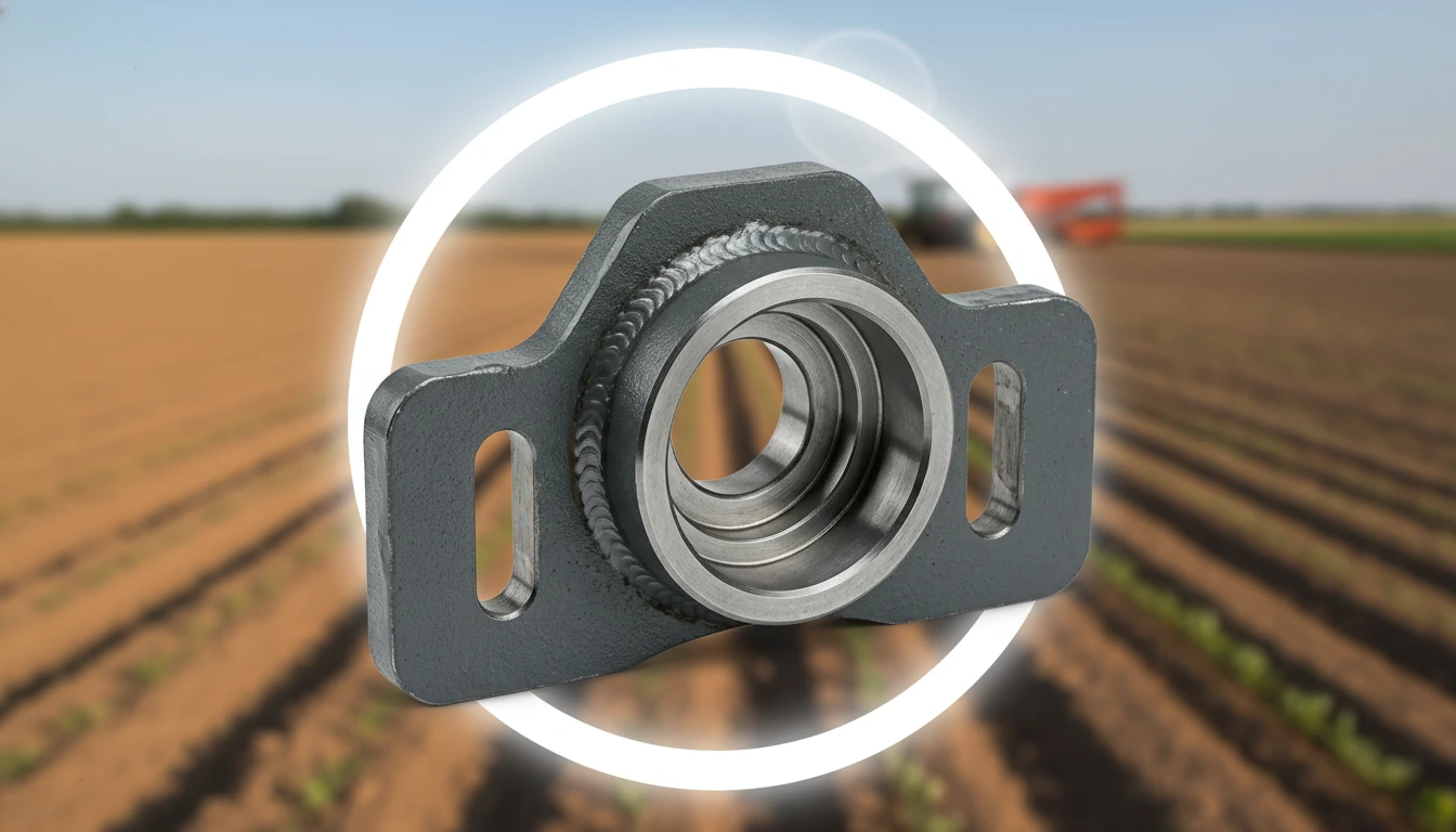
Industry Applications & Deployment Scenarios
As the front rotor-shaft support on any 4.0 m header with a front-exit rotor shaft, the Front Bearing Housing Welding appears across a considerably wider range of machinery than primary rotary tillage alone — anywhere the same front-mounted, PTO-driven rotor architecture is used.
Maintenance Schedule & Bore Condition Monitoring
The housing's maintenance programme has two distinct tracks: the bearing and seal service programme that follows time-based intervals, and the housing structural condition monitoring programme that tracks the two distinct failure modes — bore ovality from outer-race creep and coating failure leading to flange-face corrosion. Both are necessary to catch problems before they escalate.
Every 50 h
- Hold the back of your hand 5 cm from the housing — elevated warmth above ambient during operation indicates bearing over-load or inadequate grease
- Listen for grinding or rumbling near the front bearing zone at idle PTO speed — noise escalation is the earliest detectable sign of bearing degradation
- Inspect outer coating for chips and bare-metal patches; touch-up with cold zinc spray before next shift
- Check M12 mounting bolts for seating — feel for any play under firm lateral hand pressure
Every 200 h
- Remove seal plate; inspect lip seal for lip cracking, hardening, or visible wear groove — replace if any are visible
- Re-grease: remove old grease, re-pack to 30% fill volume with fresh NLGI #2, refit seal plate with new gasket
- Re-torque all M12 mounting bolts to 90 N·m after initial settling period
- Measure bore diameter at three angular positions with an internal dial gauge — ovality ≥ 0.05 mm warrants housing and bearing replacement planning
- Inspect shaft journal for fretting corrosion at bearing seating length
End of Season
- Remove housing completely; wash bore and mounting face with degreasing agent, rinse and dry
- Measure bore diameter at three angles and two axial positions — document values for next-season comparison
- Inspect mounting flange face for corrosion pitting using a magnifying glass; pitting ≥ 0.3 mm deep warrants replacement before next season
- Replace bearing and seal if cumulative seasonal hours exceed 600
- Apply rust-preventive oil to all unmachined exterior surfaces before winter storage
Replace Immediately — Bore Ovality ≥ 0.05 mm:
When the bearing bore measures ≥ 0.05 mm oval at any cross-section, the H7 interference fit has been lost and the bearing outer race can rotate freely within the bore — outer-race creep. Creep generates fretting corrosion between bore wall and outer race, producing iron oxide powder that enters the bearing grease and causes catastrophic abrasive wear of rolling elements within 50–100 hours. There is no repair for an oval bore — the housing must be replaced. Bearing retainer compound is a temporary measure that delays, but does not prevent, eventual bore-wall collapse when the compound degrades under the thermal cycling of field service.
Market Pricing & Five-Year Value Analysis
Unit price is a misleading guide to housing value because the downstream bearing and seal replacement costs from bore ovality in lower-quality housings dominate the total cost of ownership. The 5-season analysis below uses 300 operating hours per season and includes bearing, seal, and labour costs attributable to housing bore quality variation across supply tiers.
| Supply Tier | Unit Price (USD) | Housing Life (Seasons) | Bearing Replacements / 5 Yr | 5-Year TCO (USD) |
|---|---|---|---|---|
| OEM Factory Part Authorised dealer channel |
$95 – $145 | 4 – 7 | 2 – 3 | $230 – $380 |
| Premium Aftermarket Established brand, CNC-bored |
$52 – $82 | 3 – 5 | 3 – 4 | $195 – $310 |
| EVER-POWER ★ Recommended Factory-direct, H7 CMM-verified, 500 h coating |
$38 – $60 | 4 – 6 | 2 – 3 | $140 – $235 |
| Generic / No-CMM Verification Unverified bore, no material certificate |
$12 – $28 | 0.5 – 1.5 | 5 – 8 | $290 – $520 |
Prices are indicative ex-works; exclude freight and import duties. TCO includes housing cost plus bearing, seal, and labour costs attributable to bore-quality differences. Contact [email protected] for current volume-tier pricing.
Sustainability, Compliance & Key Export Markets
EVER-POWER supplies the Front Bearing Housing Welding to distributors and OEM customers across more than 20 countries. The major export markets each carry regulatory and documentation requirements that EVER-POWER's compliance infrastructure addresses proactively.
China — Largest Market
China's domestic 4.0 m rotary tiller aftermarket is the world's largest by unit volume. EVER-POWER materials are procured against GB/T 700 mill certificates. The ISO 9001:2015 facility satisfies China's agricultural machinery subsidy programme documentation requirements. Laser-cutting steel scrap is 100% recycled through contracted mills, and the powder coating line uses zero-VOC formulations compliant with China's GB 30981 industrial emission standard.
European Union — CE Compliance
EU Machinery Directive 2006/42/EC requires structural bearing-support components to meet minimum design standards. EVER-POWER supplies welding PQR documentation, GB/T 700 material declarations, and CMM reports suitable for CE technical file preparation. Italy, France, and Germany are the three highest-volume EU buyers. The coating system complies with EU REACH Regulation 1907/2006 — no SVHC substances are present in primer or topcoat formulations.
India, Vietnam & Bangladesh
South and Southeast Asia represent the fastest-growing export segment. BIS (India) and TCVN (Vietnam) import documentation requirements for HS Code 8432.80 are bundled into EVER-POWER's standard export package. EVER-POWER's distributor network in Punjab, India maintains local housing stock to serve the sub-continent's intensive spring and post-monsoon tiller maintenance calendar.
Environmental Position
The housing's 4–6 season service life reduces material consumption per unit of agricultural output compared to generic alternatives requiring replacement every 1–2 seasons. Shot-blast wastewater is processed through a closed sediment-filter loop meeting China GB 8978 standard. The part contains no deliberate heavy-metal additions subject to EU RoHS Directive 2011/65/EU.
EVER-POWER vs. Market Alternatives
For a bearing housing, the specifications that separate long-lived precision units from early-failure catalogue parts require the most production discipline to achieve — and are the ones most commonly omitted under cost pressure. The seven criteria below show where EVER-POWER's manufacturing process produces measurable field advantages.
| Criterion | OEM Brand | Generic Aftermarket | EVER-POWER |
|---|---|---|---|
| Bearing Bore Tolerance | H7 typical | Uncontrolled | H7, post-assembly, CMM 100% |
| Seal Face Flatness | ≤ 0.05 mm typical | 0.1 – 0.5 mm common | ≤ 0.05 mm, 100% CMM |
| Post-Weld Bore Drilling | Yes | Often pre-weld | Always post-weld + 6 h settle |
| Material Certificate | Proprietary | Rarely available | GB/T 700 per batch |
| Corrosion System | Powder coat | Single coat paint | Zn primer + powder ≥ 500 h SST |
| CMM Report per Unit | On request | No | Standard with shipment |
| OEM / Private Label | No | Limited | Full OEM from 5 pcs |
Customer Success Cases & Field Performance Data
Three field cases drawn from distributor reports over the 2021–2024 seasons illustrate the bearing bore retention, corrosion resistance, and operating cost impact of the Front Bearing Housing Welding in distinct environments.
Frequently Asked Questions
Technical and procurement guidance for the Front Bearing Housing Welding. For drawing pre-checks or engineering queries, contact [email protected].
Quality Documentation Available
Mill test certs · Welding PQR · CMM bore inspection reports · Salt-spray test certificates — all available on request per production batch.
Related products


We promise will offer the best price by the high quality in china! We also accept special order about the products. If you are interested in our products. Please do not hesitate to let us know.We are pleased to give you the detailed information.We promise that our products would be safety and were in high quality and reasonable price. If you are interested in our products, please contact us asap.We are sincerely looking for your cooperation.
Most of our products are exported to Europe or Americas, both standard and nonstandard products available. We can produce as per your drawing or sample. Material can be standard or as per your special request. If you choose us, you choose reliable.
Industries We Service
