Slewing Drive
HZPT slewing drive is a gearbox designed to handle radial or axial loads using high rotational torque. In addition, the slewing ring bearing, at the heart of the drive, enables it to withstand high overhung or moment loads. A descendant of the “worm” screw, slewing drives are present in construction machinery, manufacturing, military equipment, and many other applications that require strength and precision.
The physics of the slew drive makes it a versatile solution for many applications. In operation, the slew drive’s axial movement, or motion around its axis, interacts to create radial torque. The action occurs by meshing the grooves of the horizontal screw with the teeth of a perpendicular gear. While turning, the worm gear’s axial movement transfers magnified torque force to the radial gear. The number of threads on the horizontal screw and the number of gears that interact will determine the speed ratio of the setup.
Slew drives work best for applications in which high torque can create precision positioning and rotational accuracy. This design results in a device that works smoothly and powerfully with minimal backlash.
Showing 1–30 of 174 resultsSorted by popularity
-
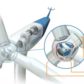
Pitch Drive Planetary Gearbox Reducer For Wind Turbine
-
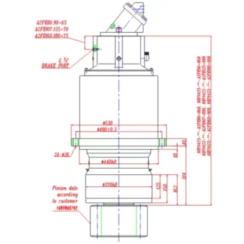
714S3 Slewing Drive Planetary Gearbox
-
710CS3 Slewing Drive Planetary Gearbox
-
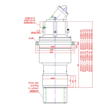
710CS2 Slewing Drive Planetary Gearbox
-

710S2 Slewing Drive Planetary Gearbox
-
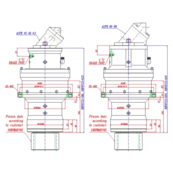
707S3 Slewing Drive Planetary Gearbox
-
707S2 Slewing Drive Planetary Gearbox
-
715S3 Slewing Drive Planetary Gearbox
-
710DS3 Slewing Drive Planetary Gearbox
-
710DS2 Slewing Drive Planetary Gearbox
-
710BS3 Slewing Drive Planetary Gearbox
-
709S3 Slewing Drive Planetary Gearbox
-
709S2 Slewing Drive Planetary Gearbox
-
706S3 Slewing Drive Planetary Gearbox
-
706S2 Slewing Drive Planetary Gearbox
-
715L3 Slewing Drive Planetary Gearbox
-
713L3 Slewing Drive Planetary Gearbox
-
711L Slewing Drive Planetary Gearbox
-
709L Slewing Drive Planetary Gearbox
-
707L Slewing Drive Planetary Gearbox
-
706L Slewing Drive Planetary Gearbox
-
705L Slewing Drive Planetary Gearbox
-
711AL Slewing Drive Planetary Gearbox
-
709AL Slewing Drive Planetary Gearbox
-
707AL Slewing Drive Planetary Gearbox
-
706AL Slewing Drive Planetary Gearbox
-
705AL Slewing Drive Planetary Gearbox
-
703AL Slewing Drive Planetary Gearbox
-
701L Slewing Drive Planetary Gearbox
-
700L Slewing Drive Planetary Gearbox