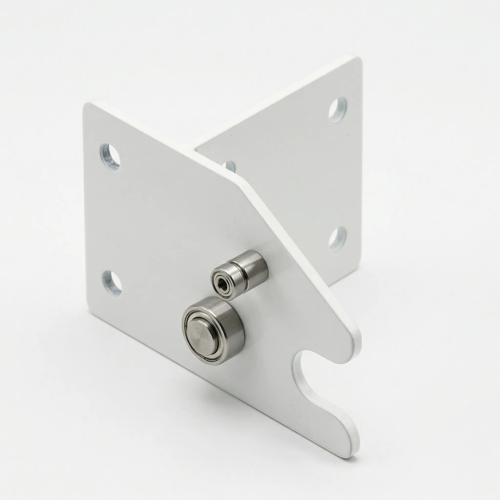
Front Upper Locating Plate Welding

The Front Upper Locating Plate Welding serves as a critical datum component for 4.0 m rotary tiller headers. Made from Q235B steel, it features post-weld CNC-drilled H8 bores (±0.027 mm) and verified flatness ≤0.5 mm/300 mm. Advantages include superior alignment accuracy, exceptional fatigue resistance, dual-layer corrosion protection (≥480 h salt-spray), direct bolt-on fit with major platforms, and reliable multi-season performance in high-vibration field conditions.
Product Specifications
Front Upper Locating Plate Welding · EVER-POWER Header Precision Fabrication Division
| Parameter | Specification | Remarks |
|---|---|---|
| Product Name | Front Upper Locating Plate Welding (前上定位板焊合) | Header frame datum component |
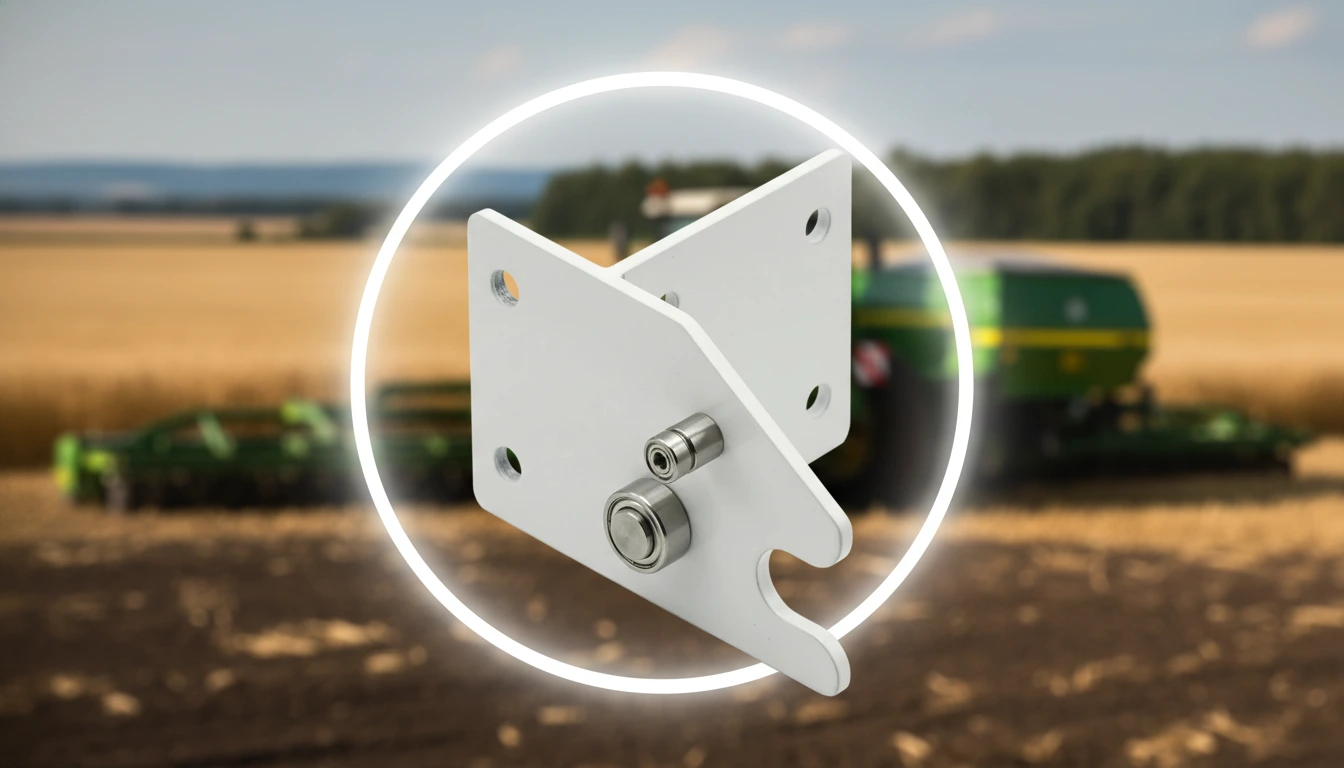
| Application Platform | 4.0 m Rotary Tiller / Rotavator Header Frame | S4.0 series front upper section |
| Primary Material | Q235B Cold-Rolled Structural Steel | GB/T 700 certified; yield ≥ 235 MPa |
| Plate Thickness | 6 mm (standard) / 8 mm (reinforced option) | Reinforced for high-vibration platforms |
| Welding Standard | GB/T 12467 / AWS D1.1 CO₂ MIG | Full-penetration at structural joints |
| Locating Hole Tolerance | H8 (±0.027 mm on Ø20 reference bores) | CNC-drilled after assembly tack |
| Positional Flatness | ≤ 0.5 mm over 300 mm reference span | CMM verified post-fabrication |
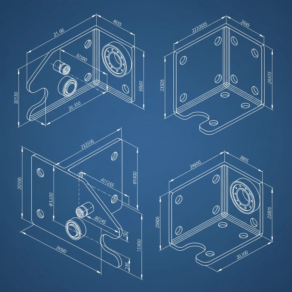
| Overall Dimensions | Approx. 340 × 180 × 60 mm | Varies by model sub-variant |
| Net Weight | ≈ 4.2 kg (standard) / ≈ 5.6 kg (reinforced) | Excl. mounting hardware |
| Surface Treatment | Sa 2.5 Shot-Blast + Epoxy Primer + Powder Coat | Salt-spray ≥ 480 h (ISO 9227) |
| Mounting Holes | 4× M10 through-bolt + 2× Ø20 locating pins | ISO-pitch header frame pattern |
| Standard Colour | Agricultural Red (RAL 3020) / Custom RAL | OEM colour matching from 10 pcs |
| Compatible Header Width | 4,000 mm (4.0 m) rotary tiller header | Front upper frame zone |
| MOQ / Lead Time | 1 piece / 7–14 days ex-works | OEM packing and labelling available |
Why the Front Upper Locating Plate Matters for Header Accuracy
In any precision-assembled machine, a datum component is not the most glamorous part in the catalogue — but remove it or replace it with a dimensionally inferior substitute, and every measurement that was referenced to it becomes unreliable. The Front Upper Locating Plate Welding fills exactly this role on the 4.0 m rotary tiller header. Positioned at the front upper zone of the header frame, it provides the positional reference from which the gearbox housing, rotor-shaft bearing brackets, PTO driveline alignment, and three-point hitch connection geometry are all ultimately derived. When this plate is welded and machined to correct flatness and hole-centre accuracy, the entire header assembly comes together with the tolerances the machine designers specified. When it is not — either through manufacturing variance or wear-induced distortion in service — progressive misalignment propagates through the drivetrain, shortening bearing life, increasing PTO driveline angularity, and eventually causing vibration levels that affect crop processing quality.
This component's role as a header component is structural in two distinct senses. Geometrically, it carries the locating pin bores that index the gearbox mounting bracket to a fixed position relative to the header frame — a function that demands hole-centre accuracy to ±0.027 mm under the H8 tolerance assigned to Ø20 mm locating bores. Mechanically, it must transfer the static and dynamic load between the gearbox bracket and the frame during operation without deflecting enough to shift those bore centres beyond the bearing clearance budget of the PTO-input shaft bearings. At full-rated PTO torque on a 4.0 m rotor operating in heavy clay soil, the peak radial load at the front gearbox mounting can exceed 4 kN — a load that demands a locating plate with genuine structural reserve rather than the nominal flatness and hole tolerance that catalogue-grade alternatives offer.
EVER-POWER manufactures this component within a dedicated precision fabrication cell that combines CNC laser-cutting, fixture-controlled tack welding, MIG full-penetration welding, and post-assembly CNC drilling in a single traceable production flow — the sequence that is necessary to achieve the 0.5 mm flatness and H8 bore tolerance specifications that are printed on the drawing but often absent from the actual dimensions of cost-driven aftermarket alternatives.
Design Features That Solve Real Alignment Problems
The market for replacement locating plate weldments is populated by parts that are difficult to distinguish in a product photograph but diverge dramatically in the field. The features described below each address a specific, documented failure mechanism found in returns analysis and distributor feedback. None of them are decorative.
Post-Assembly CNC Bore Drilling
The two Ø20 mm locating pin bores are CNC-drilled as a final operation after the plate and bracket flanges are fully welded and stress-settled — not before welding, as is common in cost-driven production. Drilling before welding allows the subsequent heat input to shift the bores from their nominal centres by up to 0.8 mm. EVER-POWER's post-assembly drilling holds bore centres within ±0.2 mm of nominal, within the H8 tolerance band that the gearbox locating-pin fit requires.
CMM-Verified Plate Flatness
Every finished plate is measured at eight reference points on a coordinate measuring machine before acceptance. The specification of ≤ 0.5 mm flatness over any 300 mm span is verified, not assumed. Parts that exceed this tolerance during CMM audit are returned to the machining cell for correction — no disposition waivers are granted, because flatness deviation creates gasket gaps in the gearbox bracket sealing face that produce oil leaks within the first season.
Fixture-Controlled Tack Sequence
All sub-components are loaded into a dedicated steel fixture that enforces the nominal assembly geometry to ±0.5 mm before any tack weld is placed. This eliminates the manual alignment errors that accumulate in standard fabrication shops where components are held by hand or generic clamps. The fixture geometry is CMM-verified at the start of each batch, and any fixture wear that shifts the nominal geometry beyond 0.3 mm triggers a fixture recalibration before production continues.
Dual-Layer Corrosion Protection
Sa 2.5 shot-blast establishes a clean anchor profile before the zinc-rich epoxy primer at ≥ 55 µm DFT is applied. An electrostatic powder topcoat at ≥ 80 µm DFT follows, cured at 185 °C. The combined system passes 480 hours of neutral salt-spray testing per ISO 9227. For a component that spends its working life exposed to soil spray, crop moisture, and agricultural chemical residues, this coating system is what separates a three-season part from a one-season part.
ISO-Standard Bolt Pattern
The four M10 mounting holes are drilled to the ISO-pitch header frame rail standard used across the Kubota, Yanmar, and Dongfeng 4.0 m platforms — the three highest-volume machines in the global 4.0 m class. This means the EVER-POWER locating plate is a genuine direct-replacement part for the majority of in-service machines without requiring any re-drilling, shimming, or custom spacer fabrication that would re-introduce the positional errors the original plate was designed to eliminate.
Edge-Ground Laser Cut Profiles
All cut edges on the mounting flange and locating bracket faces are ground to remove dross, micro-notches, and hardened re-cast zones left by the laser cutting process. This grinding step, which many suppliers omit for cycle-time reasons, eliminates the stress-concentration points that drive fatigue cracking at bracket edges under the high-frequency vibration environment of rotary tilling. Ground edges also produce a cleaner seating surface that reduces gasket deformation at the gearbox bracket interface.
Production Workflow — Seven Controlled Stages
Seven sequential production stages govern every Front Upper Locating Plate Welding that leaves EVER-POWER's precision fabrication cell. The most critical discipline that separates this part from standard aftermarket alternatives is the placement of CNC drilling after all welding and thermal operations — the sequence that ensures the locating bore positions are not subsequently disturbed by welding heat.
① Material Procurement & Batch Verification
Q235B cold-rolled plate arrives with GB/T 700 mill test certificates. EVER-POWER's QC team performs independent Brinell hardness checks and spectroscopic spot-checks on each incoming coil. Plate that fails the carbon content check (C ≤ 0.22% specification) or shows surface lamination defects on ultrasonic scanning is quarantined and returned — it is not re-approved through a concession process. Clean material release is the first prerequisite for dimensional consistency in the finished part.
② Fibre-Laser Blanking & Edge Grinding
A 6 kW fibre-laser platform cuts all plate blanks and bracket flanges to ±0.2 mm positional accuracy. Immediately after cutting, all edges on the bracket faces, seating surfaces, and corner radii are hand-ground to remove the hardened dross and micro-notches introduced by the laser thermal cycle. This grinding step is what prevents the fatigue cracks that appear at unground laser edges within 200–400 vibration-hours in rotary tilling service.
③ Fixture Jigging & Tack-Welding
All blanks and flanges are loaded into the purpose-built steel fixture and clamped against machined locating stops before any tack weld is applied. The fixture enforces nominal geometry to ±0.5 mm across the full 340 mm plate span. A deliberate back-step tacking sequence minimises angular distortion at the corner welds before full-seam welding begins. The fixture is CMM-verified at the start of each production batch to confirm accumulated wear has not compromised the locating stop positions.
④ Full-Penetration CO₂ MIG Welding
Qualified welders complete all structural welds using CO₂-shielded MIG with parameters defined in the pre-qualified procedure qualification record (PQR). All bracket-to-plate junction welds receive full-penetration profiles per GB/T 12467 — a requirement that exceeds the fillet weld minimum of many competing weldments. The back-step weld sequence continues through the full-seam stage to control thermal distortion of the locating plate face to the minimum achievable before the CMM check.
⑤ CNC Drilling of Locating Bores & Mounting Holes
After the assembly has fully cooled to ambient temperature — a settling period of minimum 4 hours — it is fixtured on the CNC machining centre from a reference datum face established on the locating plate's flat face. All Ø20 mm locating bores and M10 mounting holes are drilled from this single datum to eliminate accumulated positional error. Bore diameter is finish-reamed to H8 tolerance. CMM measurement of bore centre distances follows immediately, and the result is stamped on the unit's production record card.
⑥ Blast Cleaning & Dual-Layer Coating
Machined bores and the locating plate seating face are masked. The exterior is Sa 2.5 shot-blasted, then zinc-rich epoxy primer is applied at ≥ 55 µm DFT followed by electrostatic powder topcoat at ≥ 80 µm DFT, cured at 185 °C for 20 minutes. Film-thickness is measured at six positions per part. Any reading below specification triggers rework — there are no pass waivers in the coating process, because coating failures on this component allow corrosion to pit the locating plate face, causing gasket leak paths that develop within a single season.
⑦ Final CMM Audit, Record & Export Packing
Each finished part is measured at 8 critical dimensions — plate flatness, bore centre spacing, bore diameter (H8 check), hole pitch dimensions — on a coordinate measuring machine before acceptance. Accepted units receive bore protector caps on all machined surfaces, are wrapped in VCI polyethylene film, and packed in formed cardboard inner with foam inserts protecting the locating plate seating face. The CMM report is stored against the unit's QC serial number and is included in the export documentation package on request.
Material Specification & Engineering Rationale
The material choice for a locating plate weldment is governed by three intersecting requirements: weldability without distortion, surface hardness adequate to resist the fretting wear generated by the gearbox bracket locating pins in service, and sufficient flatness stability under the thermal cycling of outdoor operation. Q235B satisfies all three more reliably than higher-strength grades in this application.
Q235B Cold-Rolled Steel — Main Plate Body
Q235B (yield ≥ 235 MPa, tensile 370–500 MPa) is selected over Q345B for the main plate body because its lower carbon content (C ≤ 0.22%) produces significantly less weld-shrinkage distortion during MIG welding of thin-to-medium sections. The locating plate's flatness requirement of ≤ 0.5 mm depends on minimising weld distortion — not on maximising yield strength — and Q235B's weldability advantage translates directly into a more consistently flat finished plate at the same fabrication cost.
ER49-1 Welding Wire — Deposited Metal
ER49-1 (AWS ER70S-3 equivalent) wire deposits tensile strength ≥ 490 MPa with low silicon content, minimising the weld-spatter that contaminates the seating face during welding. Lower silicon also produces a cleaner weld-bead profile that reduces the grinding required to achieve the flush weld-toe geometry needed at the bracket-to-plate joints. The deposited metal's Charpy impact toughness of ≥ 47 J at −20 °C covers the cold pre-dawn operation temperatures common in early-spring paddy tillage in northern China and Punjab, India.
Zinc-Rich Epoxy Primer — Active Corrosion Defence
At ≥ 55 µm DFT, the zinc-rich epoxy primer provides cathodic protection at coating breach sites — zinc particles sacrifice themselves electrochemically to prevent base-metal corrosion at scratches or impact points. This is the same protective mechanism as hot-dip galvanising, implemented as a coating, and it keeps the locating plate face corrosion-free at the point that matters most: the seating surface where the gearbox bracket contacts the plate and any gap caused by corrosion pitting will produce a misalignment in the gearbox mounting geometry.
Related Components & Interfacing Parts
The Front Upper Locating Plate Welding is the positional hub of the header's front upper zone — multiple mechanical and structural components reference it directly or indirectly. When this plate is being replaced, the parts listed below should be inspected and renewed where necessary to prevent the misalignment that caused the original plate's failure from being reproduced in the new installation.
Machine Compatibility & Fitment Reference
The locating plate's M10 bolt pattern and locating pin bore centres are dimensioned to the ISO-pitch front upper frame standard used across the major 4.0 m rotary tiller platforms. Confirmed fitment data from distributor dimensional surveys is provided below. For platforms not listed, send the front frame drawing or OEM part number to [email protected] for a free pre-order compatibility check.
| Brand / Platform | Header Width | Fitment Status | Notes |
|---|---|---|---|
| Kubota KRL-400 / KRH-400 | 4.0 m | DIRECT FIT | Confirmed 2018–2024 production |
| Yanmar RS400 / RA400 | 4.0 m | DIRECT FIT | Verify pin-bore depth before order |
| Dongfeng DF-400 Series | 4.0 m | DIRECT FIT | Standard GB bolt pattern |
| Maschio Gaspardo DH 4000 | 4.0 m | MINOR ADAPT. | Pin-bore depth varies ±4 mm; send drawing |
| Landini / AGCO 4.0 m Header | 4.0 m | CONFIRM DIMS | Submit frame drawing for pre-check |
| Generic ISO 4.0 m Frame | 4.0 m | SEND DRAWING | Free check; 1-day response |
Step-by-Step Replacement Procedure
Replacing the front upper locating plate on a rotary tiller header is a relatively compact workshop task — the part itself is small — but the alignment consequences of a poorly executed replacement are large. The six steps below reflect best practice from dealer feedback across China, India, and Italy's main tiller-servicing regions.
Shut Down & Block Header
Disengage PTO, switch off engine, remove key, and block the header on stands before reaching inside the front frame zone. The gearbox is immediately above the locating plate — confirm all rotating elements are stationary before loosening any fasteners in this area.
Remove Gearbox Bracket
Support the gearbox assembly before removing the bracket fasteners — the gearbox is heavy and will drop without support. Once the bracket is free of the locating pins, measure the bracket's pin-bore diameters with an internal dial gauge and record the measurements for the root-cause analysis before discarding the old hardware.
Remove Old Locating Plate
Remove all four M10 mounting bolts. If bolts are seized, apply penetrating fluid and allow 15 minutes — do not force seized Grade 10.9 bolts, as shearing the head leaves a stud removal job that takes far longer than waiting for penetrant to work. Note the orientation of any shim washers before removing.
Inspect & Prepare Frame Rail Face
Wire-brush the frame rail mating face and check it with a precision straight-edge. Any high spot above 0.3 mm — from weld spatter, corrosion pitting, or impact distortion — must be dressed down before the new plate is installed. High spots on the rail face translate directly into flatness errors in the new plate's installed position.
Install & Torque New Plate
Fit new Grade 10.9 M10 bolts with hardened washers and engage all four finger-tight before introducing any torque. Torque in a diagonal cross-pattern in three stages to 55 N·m (M10, Grade 10.9, lightly oiled threads). Confirm the plate seats flush to the frame face — rock it with a fingertip before final torque to detect any remaining high-spot on the frame that needs additional dressing.
Refit Bracket & Verify PTO Alignment
Fit new locating pins and new sealing gasket. Lower the gearbox bracket onto the locating pins and torque the bracket bolts to the machine manufacturer's specification. Before restarting, check the PTO driveline angularity at full operating position using a protractor — any angle above 5° at either universal joint should prompt a re-check of the locating plate position before first operation.
Industry Applications & Deployment Scenarios
As a positional datum component for the front upper gearbox mounting zone, the Front Upper Locating Plate Welding appears across any machinery platform that uses a front-mounted PTO-driven header with a centrally positioned gearbox — a configuration that extends across several sectors beyond agricultural tillage.
Maintenance, Inspection & Alignment Monitoring
The front upper locating plate is a structural datum component — its maintenance programme is primarily an inspection regime aimed at detecting the early signs of position drift, corrosion damage to the seating face, and locating pin wear before they compromise gearbox alignment. The three time-based inspection windows below align with standard tractor service intervals.
Every 50 h
- Visual inspection of the plate's outer face for coating damage at impact zones
- Confirm all four M10 mounting bolts are fully seated — check for movement under firm lateral hand pressure
- Look for PTO vibration changes during first 5 minutes of operation — a sudden increase can indicate locating pin looseness
- Touch-up coating chips with cold-zinc spray before next operating shift
Every 200 h
- Re-torque all M10 mounting bolts to 55 N·m after initial bolt-settling period
- Remove gearbox bracket and inspect locating pin-to-bore fit — replace pins if diameter has worn below nominal by ≥ 0.1 mm
- Check plate seating face for corrosion pitting; treat any pitting ≥ 0.3 mm deep with cold zinc spray before refitting
- Verify PTO driveline angularity with a protractor — deviation above 5° warrants locating position re-check
End of Season
- Remove gearbox bracket completely; wash plate seating face and pin bores
- Apply thread-lock compound to mounting bolt holes after cleaning
- Measure pin-bore diameters with internal gauge; document for next season comparison
- Apply light coat of rust-inhibitor spray to all bare steel visible through coating damage
- Check plate flatness by laying it against a straight-edge; replace if deviation exceeds 0.8 mm
Mandatory Replacement Trigger — Plate Face Flatness > 0.8 mm:
Once the locating plate face deviates beyond 0.8 mm from flat at any location across its 300 mm reference span, the H8 locating pin bores can no longer guarantee the gearbox bracket is held in its designed position regardless of how correctly the locating pins are fitted. A distorted plate face creates a rocking condition in the bracket seating that progressively wears the locating pin bores beyond their tolerance band, producing a chain of alignment errors that ultimately manifests as elevated PTO shaft vibration and bearing noise. Do not attempt to flatten a distorted locating plate by re-welding or pressing — these operations introduce new residual stresses that shift the bore centres and invalidate the part as a datum reference. Replace the plate.
Market Pricing & Value-Over-Life Analysis
The aftermarket for locating plate weldments appears to converge on a narrow price band across tiers, but this convergence is misleading because the downstream cost of alignment drift — in bearings, gearbox seals, and PTO shaft fatigue — varies enormously between a correctly-dimensioned plate and a catalogue-grade alternative. The five-season analysis below uses 300 working hours per season and includes the downstream bearing and seal replacement costs attributed to gearbox position variance from imprecise locating plates.
| Supply Tier | Unit Price (USD) | Plate Life (Seasons) | Bearing & Seal Cost / 5 Yr | 5-Year TCO (USD) |
|---|---|---|---|---|
| OEM Factory Part Authorised dealer channel |
$85 – $130 | 4 – 6 | $80 – $120 | $165 – $280 |
| Premium Aftermarket Established brand, CNC-drilled |
$42 – $68 | 3 – 5 | $120 – $180 | $165 – $260 |
| EVER-POWER ★ Recommended Factory-direct, CMM-verified, H8 bores |
$28 – $46 | 4 – 6 | $80 – $120 | $108 – $196 |
| Generic / Non-CMM-Verified No material cert., manual drilling |
$10 – $22 | 0.5 – 1.5 | $280 – $480 | $310 – $540 |
Prices are indicative ex-works; exclude freight and import duties. TCO includes plate unit cost plus bearing, seal, and gearbox oil-seal replacement costs attributable to gearbox position variance between tiers. Contact [email protected] for current volume-tier pricing.
Sustainability, Compliance & Key Export Markets
EVER-POWER supplies the Front Upper Locating Plate Welding to distributors across more than 20 countries. The markets with the highest purchase volumes each carry distinct regulatory and documentation requirements that EVER-POWER's export compliance infrastructure is built to address.
China — Largest Volume Market
China's domestic aftermarket for rotary tiller header components is the world's largest by unit volume. EVER-POWER materials are procured against GB/T 700 (Q235B) mill test certificates. The ISO 9001:2015 production facility satisfies the documentation requirements of China's agricultural machinery purchase subsidy programme. Steel plate scrap from laser-cutting operations is 100% recycled through contracted mills, and the powder coating line uses zero-VOC formulations that comply with China's GB 30981 industrial coating emission standard.
European Union — CE Compliance
EU Machinery Directive 2006/42/EC requires structural components of powered agricultural machinery to meet minimum design standards. EVER-POWER supplies welding procedure qualification records (PQR), GB/T 700 material declarations, and CMM dimensional reports sufficient to support CE technical file preparation by EU-based OEM customers. Italy (the EU's largest rotary tiller producer), France, and Germany are the three largest EU buyers of this component. The coating system complies with EU REACH Regulation 1907/2006 — no SVHC substances are present in the primer or topcoat formulations used on this part.
India, Vietnam & Bangladesh
South and Southeast Asia represent the fastest-growing export markets for EVER-POWER header components, driven by mechanisation programmes expanding large-format tiller deployment into paddy regions. BIS (India) and TCVN (Vietnam) import documentation requirements for HS Code 8432.80 are bundled into the standard export package. EVER-POWER's distributor in Punjab, India manages local customs liaison and maintains stock of this component to serve the sub-continent's spring and monsoon-season tiller maintenance calendar.
Environmental Position
The locating plate's 4–6 season service life under normal operating conditions reduces the total material consumed per unit of agricultural output by replacing lower-grade alternatives less frequently. Shot-blast wastewater is processed through a closed sediment-filter loop meeting China GB 8978 standard. The part contains no deliberate addition of restricted heavy metals under EU RoHS Directive 2011/65/EU — the coating, weld wire, and base steel are all compliant with current RoHS restrictions applicable to agricultural machinery components.
EVER-POWER vs. Market Alternatives
For a datum component like the front upper locating plate, the dimensions that matter are not the ones visible on a catalogue page. The seven criteria below are the measurable technical differentiators that determine whether a replacement locating plate will maintain gearbox alignment across its service life or gradually allow it to drift.
| Technical Criterion | OEM Brand | Generic Aftermarket | EVER-POWER |
|---|---|---|---|
| Material Cert | Proprietary | Rarely available | GB/T 700 per batch |
| Locating Bore Tolerance | H8 typical | Uncontrolled | H8, post-assembly, CMM |
| Plate Flatness | ≤ 0.5 mm typical | 1 – 2 mm common | ≤ 0.5 mm, 100% CMM |
| Edge Grinding | Model-dependent | Omitted | All load-bearing edges |
| Corrosion System | Powder coat | Single coat paint | Zn primer + powder ≥ 480 h SST |
| OEM / Private Label | No | Limited | Full OEM from 5 pcs |
| CMM Report per Unit | On request | No | Standard with shipment |
Customer Success Cases & Field Performance Data
The three case summaries below are drawn from distributor field reports submitted over the 2021–2024 operating seasons. Each addresses a specific alignment and durability performance dimension of the Front Upper Locating Plate Welding in a distinct operational environment.
Frequently Asked Questions
Technical and procurement guidance for the Front Upper Locating Plate Welding. For drawing pre-checks or engineering queries, contact [email protected].
Quality Documentation Available
Mill test certs · Welding PQR · CMM inspection reports · Salt-spray test certificates — all available on request per production batch.


We promise will offer the best price by the high quality in china! We also accept special order about the products. If you are interested in our products. Please do not hesitate to let us know.We are pleased to give you the detailed information.We promise that our products would be safety and were in high quality and reasonable price. If you are interested in our products, please contact us asap.We are sincerely looking for your cooperation.
Most of our products are exported to Europe or Americas, both standard and nonstandard products available. We can produce as per your drawing or sample. Material can be standard or as per your special request. If you choose us, you choose reliable.
Industries We Service
